艾灸应用开发文档
| 修订日期 | 修订版本 | 修订内容 | 修订人 |
|---|---|---|---|
| 2024.02.28 | V0.1 | 初始化文档 | 邓誉鑫 |
| 2024.03.06 | V0.2 | 更新开发流程 | 邓誉鑫 |
| 2024.09.10 | V0.3 | 更新使用文档 | 邓誉鑫 |
[TOC]
1 功能描述
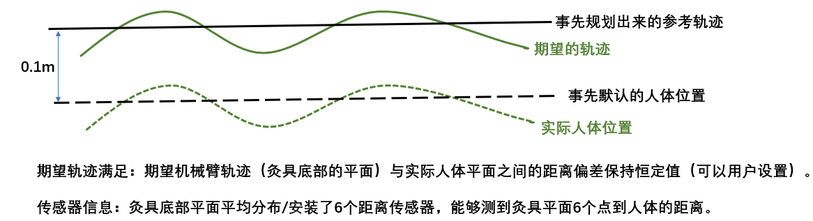
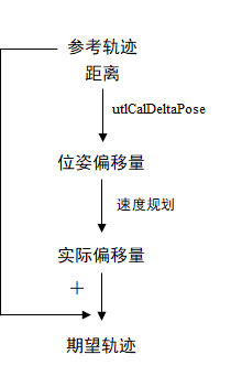
根据需求,需要通过距离传感器数据来实时调整机械臂的偏移距离及姿态,总体流程如下:
1.传入参考轨迹与传感器距离
2.通过接口utlCalDeltaPose计算工具坐标系下的位姿偏移量
3.对偏移位姿进行速度规划并进行采样得到实际偏移位姿
4.在参考轨迹上叠加实际偏移位姿得到实际轨迹,下发给机械臂运动
注:由于传感器频率与规划器采样频率不一致,需要在外层进行速度规划
计算工具坐标系下的位姿偏移量的接口定义如下:
 /**
   * @brief 通过距离计算位姿偏移量
   * @param distances: N 个距离, N >=3
   * @param position: 距离物体的保持高度
   * @param radius: 传感器中心距离末端tcp的等效半径
   * @param track_scale: 跟踪比例, 设置范围(0, 1], 1表示跟踪更快
   * @param pose_off: 位姿偏移量, 基于工具坐标系
   * @return ret < 0: 计算失败
   */
   ARAL_API_BASIC(1.0) int utlCalDeltaPose(const std::vector<double>& distances, const double& position, const double& radius, const double& track_scale, interface::RLTwist& pose_off)const = 0;
接口计算过程如下小节
2 计算偏移距离及姿态
已知:六个传感器距离 ,传感器分布半径 ,末端位姿 以及用户设定的保持高度
2.1 工具坐标系Z轴方向的距离
根据保持高度,需要调整的工具坐标系Z轴方向距离即位移增量P为:
2.2 根据距离拟合平面
首先需要正确安装距离传感器并标定工具 tcp,建立传感器相对tcp的坐标关系,如下图,传入P1~P6六个传感器对应的距离,通过传感器距离拟合一个平面,这个平面为人体表面最近接触点的法向平面,过程如下:
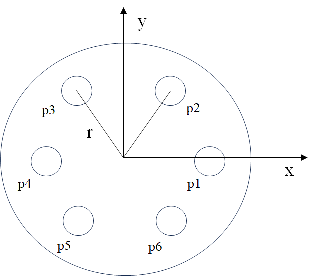
设定六个拟合点在工具坐标系下表示 将六个点(拟合平面的点)以及原点(定义平面内侧的点)传入以下接口可拟合出一个在工具坐标系下描述的平面,该平面定义为 ,法向量为
  /**
     * @brief 使用N + 1个点定义一个平面: 定义无限平面时 N >= 3,定义有限平面时 N = 3
     * @param points: 三维坐标点构成的矩阵, points = { {x1, y1, z1}, {x2, y2, z2}, ..., {xn, yn, zn} }, points.size()必须大于等于3
     * @param point_direction: 一个三维坐标点,用于规定平面内侧的方向, point_direction = {x0, y0, z0}
     * @param plane: 输出的平面
     * @return ret < 0: 无法定义平面
     */
    ARAL_API_BASIC(1.0) int utlDefinePlane(const std::vector<Array3d>& points, const Array3d& point_direction, geometric_shapes::Plane& plane)const = 0;
接口计算原理如下:
表示第 个点, 是一个矩阵, 是一个列向量, 是最小二乘解,而 是法向量
2.3 计算机器人末端z轴到拟合平面法向量的姿态变换角度
由于在工具坐标系下描述,所以工具 轴 在工具坐标系下的表示为
计算绕指定轴 的旋转角度
指定轴计算即求从当前z轴向量 到法向量 的叉积,旋转角度 为点积并求反三角函数得到
通过以上公式求得轴角( , ), 然后转化为旋转矩阵进而转化值为 角
最终接口输出位姿偏移量 pose_off = { P, }
3 使用流程
使用 otg 的速度级别规划:
otg::MoveMode::VELOCITY,采用六维规划(三维位置 + 三维姿态),使用如下接口设置速度规划的约束条件//! 设置速度规划的约束条件(会触发重新计算速度轮廓, 适用于运动约束动态变化的场景) int setConstraints(const double* maxVel, const double* maxAcc, const double* maxJ);约束条件六维,实际客户现场中,建议后三个维度(姿态维度)速度/加速度设置为前三个维度(位置维度)速度/加速度的2~3倍,以确保姿态维度跟踪能够与位置维度一致
在传感器周期内通过接口
utlCalDeltaPose计算出位姿偏移量进入速度规划层,调用以下otg接口来更新目标状态(传感器频率),将上面接口计算得到的位姿偏移量传入
tarvel中更新目标状态,具体可见例程
/**
 * @brief 更新目标状态(会触发重新计算速度轮廓, 适用于目标跟踪场景)
 * @param tarPos: 目标位置
 * @param tarVel: 目标速度
 * @param tarAcc: 目标加速度
 * @return if < 0, 表示速度规划失败
 */
 int updateTargetStates(const double* tarPos, const double* tarVel, const double* tarAcc);
- 每次规划周期内通过以下otg采样接口获取 posTraj,即采样得到的位姿变化量 (规划频率)
/**
 * @brief 按指定的时间间隔插值得到位置、速度、加速度信息,时间单位:s
 * @param posTraj: 采样位置
 * @param velTraj: 采样速度
 * @param accTraj: 采样加速度
 * @param stepTime:采样时间间隔
 * @return if = 0, 表示正常采样,if = 1, 表示采到终点,采样结束
 */
 int otgStep(double* posTraj, double* velTraj, double* accTraj, const double stepTime = 0);
- 以上求得需要调整的工具坐标系Z轴方向的位置增量 以及姿态增量 ,即位姿增量
- 由于该位姿增量在工具坐标系下描述,需要转换到基座标系下,通过以下接口求得基坐标系下描述的位姿增量
/**
 * @brief 改变 RLWrench 或 RLTwist 的作用点和参考坐标系(RLWrench 和 RLTwist变换方式一致)
 * @param ft_in_a: 输入作用在 a 点的 RLWrench 在 a 坐标系描述
 * @param F_b_a: a 相对于 b 的位姿
 * @return: 输出作用在 b 点的 RLWrench 在 b 坐标系描述
 */
ARAL_API_BASIC(1.0) RLWrench kdChangeWrenchFrame(const RLWrench& ft_in_a, const RLPose& F_b_a)const = 0;
然后通过下面接口可计算目标位姿 ,输入是初始位姿 以及位姿增量
/**
 * @brief 计算以给定速度变换单位时间后的位姿
 * @param F_w_a: 当前时刻 a 相对于 w 的位姿
 * @param da_w: 当前时刻 a 坐标系的速度在 w 的描述
 * @return 单位时间后的位姿在 w 的描述
 */
ARAL_API_BASIC(1.0) RLPose kdAddDeltaPose(const RLPose& F_w_a, const RLTwist& da_w)const = 0;
注:
1.使用该功能时必须设定机械臂的tcp
2.使用utlCalDeltaPose接口时,需要根据不同情况调整跟踪比例 track_scale,设置大跟踪速度快,设置小跟踪速度慢
3.距离传感器数据建议使用低通滤波处理以降低数据噪声
4.运动约束是六个维度,用户可以分别设置位置和姿态不同的运动约束(速度,加速度)
4 开发例程
    //! 1.数据初始化
    int ret = interface::E_STA_NO_ERROR;
    auto type = getTestType();
    std::vector<std::vector<double>> distances;
    interface::RLJntArray q0, joint;
    interface::RLPose pose_off_c, pose_off_t;
    interface::RLTwist pose_off;
    double track_scale;
    double position, radius, sample_period;
    if(type.first == 1)
    {
        ReadFromFile2D("./test/data/utl_module/test_cal_delta_pose/pose1.txt", ",", distances);
        for (size_t i = 0; i < distances.size(); ++i)
        {
            for (size_t j = 0; j < distances[i].size(); ++j)
            {
                distances[i][j] /= 1000.0;
            }
        }
        position = 0.1;
        radius = 0.05;
        q0    = {-0.64241,0.21460,0.26704,2.779,0.212,-1.063};
        joint = {-0.63803,0.19014,0.25345,2.775,0.162,-1.184};
        sample_period = 0.05;
        tcp = {0, 0, 0.3, 0, 0, 0};              // 必须设置tcp
        track_scale = 1;                         // 结合实际情况调整跟踪比例系数
    }
    if(type.first == 2)
    {
        ReadFromFile2D("./test/data/utl_module/test_cal_delta_pose/pose2.txt", ",", distances);
        for (size_t i = 0; i < distances.size(); ++i)
        {
            for (size_t j = 0; j < distances[i].size(); ++j)
            {
                distances[i][j] /= 1000.0;
            }
        }
        position = 0.1;
        radius = 0.05;
        q0    = {-0.64241,0.21460,0.26704,2.779,0.212,-1.063};
        joint = {-0.63803,0.19014,0.25345,2.775,0.162,-1.184};
        sample_period = 0.05;
        tcp = {0, 0, 0.3, 0, 0, 0};
        track_scale = 0.5;
    }

    //! 2.添加参考轨迹
    Setup(getRobotType(type.second));
    initiatePlanner(robot, q0, tcp);
    std::vector<double> max_V = {0.05, 2.0};
    std::vector<double> max_A = {4.0, 16.0};
    std::vector<double> max_J = {32.0, 128.0};
    interface::PathPoint point_r = generatePathPoint(interface::DescribeSpace::JOINT, 1, joint, {});
    interface::PathProperty path_property = generatePathProperty({0, 0}, ARAL_TP_DEFAULT_BOW_HIGH_ERR, interface::DescribeSpace::CARTESIAN);
    interface::MoveProperty move_property = generateMoveProperty(interface::MoveMode::POSITION, 0, max_V, max_A, max_J);
    ret = robot->tpAddPositionLine(point_r, path_property, move_property);
    CHECK(ret >= 0);

    //! 3.规划内采样
    double cycle = 0.005, accumulatedTime = 0.0, T = 0.0;
    int plan_ret = interface::E_PLN_OK;
    interface::TrajectoryPoint point;

    double posTraj[6], velTraj[6], accTraj[6], move_time = 0;
    std::vector<double> t;
    interface::RLJntArray pos, vel, acc;
    std::vector<double> V = {0.05, 0.05, 0.05, 0.05, 0.05, 0.05};
    std::vector<double> A = {4.0, 4.0, 4.0, 4.0, 4.0, 4.0};
    std::vector<double> J = {32.0, 32.0, 32.0, 32.0, 32.0, 32.0};
    otg::OTGInterfacePtr otg(new otg::OTGInterface(6, cycle, otg::OTGType::TypeV, otg::MoveMode::VELOCITY, otg::SyncBehavior::PHASE_SYNCHRONIZATION_IF_POSSIBLE)); // 采用六维规划(三维位置 + 三维姿态), 速度级规划
    otg->setConstraints(V.data(), A.data(), J.data());  // 设置速度规划的约束条件
    std::vector<interface::TrajectoryPoint> plan_points;
    std::vector<interface::RLJntArray> command_pos, command_vel, command_acc;
    memcpy(pos.data(), q0.data(), sizeof (double) * dof);
    memset(vel.data(), 0, sizeof (double) * dof);
    memset(acc.data(), 0, sizeof (double) * dof);
    int i = 0;
    while (plan_ret != interface::E_PLN_EXEC_EMPTY)
    {
        robot->rsUpdateJointPVA(pos, vel, acc);
        plan_ret = robot->tpUpdateCycle(cycle, point);
        accumulatedTime += cycle;
        T += cycle;
        //! 4.传感器周期内计算位姿偏量
        if(accumulatedTime >= sample_period)
        {
            ret = robot->utlCalDeltaPose(distances[i], position, radius, track_scale, pose_off);// 得到位姿偏量
            CHECK(ret >= E_NO_ERROR);

            //! 5.速度规划
            std::vector<double> pos_ = {0, 0, 0, 0, 0, 0};
            std::vector<double> acc_ = {0, 0, 0, 0, 0, 0};
            ret = otg->updateTargetStates(pos_.data(), pose_off.data(), acc_.data());   // 更新目标状态
            CHECK(ret >= E_NO_ERROR);
            accumulatedTime = 0;
            i ++;
        }
        ret = otg->otgStep(posTraj, velTraj, accTraj, cycle);
        CHECK(ret >= E_NO_ERROR);
        for(unsigned j = 0; j < 6; j++)
            pose_off_c[j] = posTraj[j];

        pose_off_t = robot->kdChangeWrenchFrame(pose_off_c, point.point.pose);          // 将采样得到的位姿增量转换为基座标系下描述
        point.point.pose = robot->kdAddDeltaPose(point.point.pose, pose_off_t);
        ret = robot->rsSetReferenceTrajectory(interface::CoordType::BASE, interface::RLPose(), point.point.pose.data(), point.xd.data(), point.xdd.data());
        CHECK(ret >= E_NO_ERROR);
        ret = robot->rsCalJointCommand(pos, vel, acc);    // 计算控制输出
        CHECK(ret >= E_NO_ERROR);
        move_time += cycle;
        t.push_back(move_time);
        plan_points.push_back(point);
        command_pos.push_back(pos);
        command_vel.push_back(vel);
        command_acc.push_back(acc);
    }
    plot(plan_points, command_pos, command_vel, command_acc, t, true);
    }